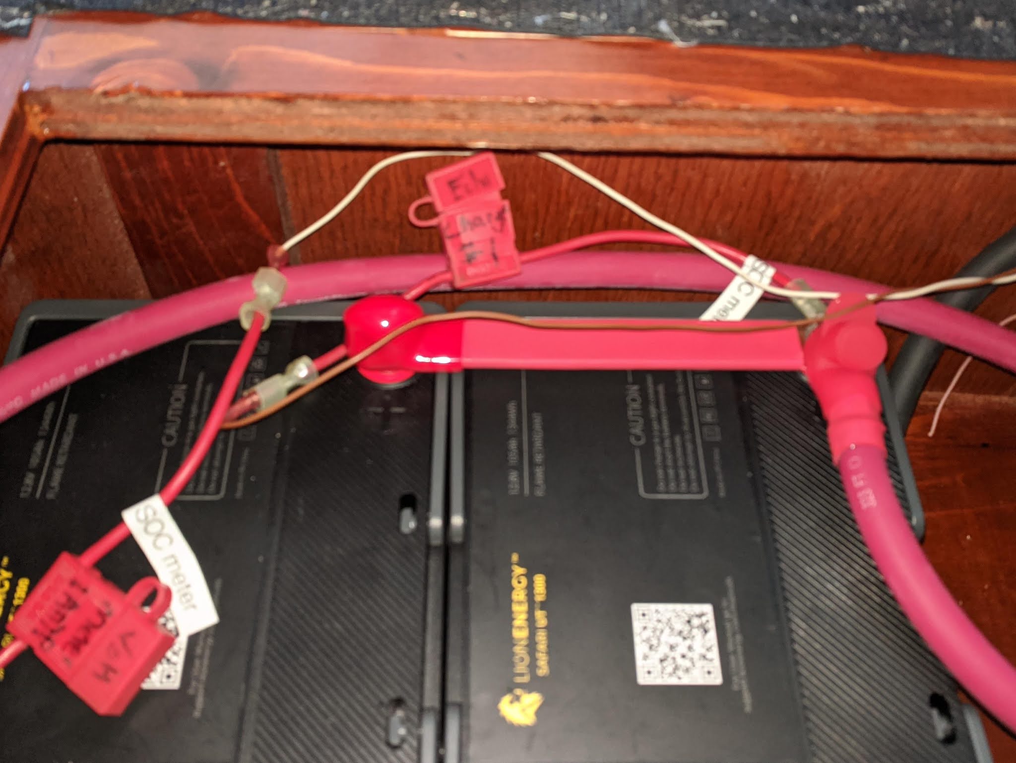
As I have mentioned in several previous posts, I just replaced our under-performing AGM batteries with lithium ion batteries, more specifically
lithium iron phosphate (LiFePO
4) chemistry "drop in" models. This post is the project write-up thus far, and will contain nothing else, so feel free to skip it if you are uninterested in such matters. I will return to our regular travelogue in my next post.
 |
New batteries installed.
|
A brief history.
When we purchased
Vector back in January of 2013, it came to us ready-to-cruise. There was a complete and functional 12-volt house electrical system, powered by five size 8D
VRLA batteries, Lifeline brand
AGM specifically. While everything was more or less working, the batteries were already damaged, with a couple having burst open their cases (really), likely due to overcharging by an internally regulated automotive alternator.
 |
| This burst case was likely due to overcharging, Photo: Steve D'Antonio |
I knew when we bought the boat that the electrical system was insufficient for how we planned to use it, and intended from the start to upgrade it. We were spoiled, coming from a bus conversion with a 24-volt system, eight 8D batteries, and a 7.5 kW main engine alternator, a system which could literally run air conditioning overnight after being charged by a day's driving.
Nevertheless, it had been sufficient for the boat's first ten years, and, with many other pressing projects, we opted to live with it as-is until we had the time and wherewithal to address it. I used the time to good effect to identify all the shortcomings and the most cost-effective ways to overcome them with an upgraded system.
 |
| Two of the six current Lifelines in their rack. I'm trying to sell them now. |
That time ultimately came a full year later, when we settled in to a
three-month stay in Stuart, Florida to join our good friends Stephanie and Martin as their new Nordhavn was being commissioned there. And while a year may sound like a long time to live with cracked battery cases and other issues, in fact we were only out cruising for less than half that time, with the remainder having been spent at marinas during our move-in and training, or in a boatyard getting all the other work done. In fact, we mostly lived in the bus during our nearly four-month boatyard stay, as the boat was too torn up to use.
The system upgrade consisted of replacing the 12-volt main engine alternator with a 24-volt model in an identical frame, increasing production from 1,820 watts up to 3,080 watts (still a far cry from the bus, with more than double that), and replacing the 12-volt inverter-charger with a 24-volt model, increasing power capacity from 2,500 watts to 4,000 watts while at the same time increasing battery charging, from 1,900 watts to 3,000 watts.
The change in voltage meant going to an even number of batteries, so we repurposed one of the two 8D starting batteries, and we bought six nice new Deka AGM batteries to replace the six old ones. I added a battery equalizer to allow us to draw all the 12-volt loads off the center-tap of the new battery bank, and re-wired the whole shebang, mostly re-using the 4/0 cables from the old system. I wrote about the project, complete with photos of the battery installation in
this post, wherein I promised that an actual project write-up was forthcoming. In reality, it was another six years before I
got around to doing that.
 |
| Inside each heavy corrugated UN3480-labeled shipping box, was this thinner retail package, replete with marketing. Do they sell these in showrooms? |
LiFePO
4 battery systems were already in consumer deployment at this time, with commercial systems available off-the-shelf. Also, our good friends and
lithium trailblazers Cherie and Chris had already been running their roll-your-own bank on their classic GM bus conversion for over two years. So you might be wondering why did we not just include lithium as part of this major and laborious upgrade to begin with.
Two factors conspired against lithium at that time. The first was that our battery racks are in the engine room, not easily relocated, and the temperature near the racks often exceeds 120° under way. Lithiums cannot be charged at this temperature, and it shortens their lifetime even to live in this kind of environment. Even if we could work around that problem, the second was expense: roll-your-own systems will not pass an insurance survey, and the only rated system on the market at that time was prohibitively expensive on a cost-per-kWh basis. I should note here that weight savings is not a factor for us.
 |
| The batteries were well-packed in this closed-cell foam. But on one of them, they inserted the foam the wrong way and the posts missed the intended holes. This could easily have cracked the case if the box had been dropped. |
Those Deka AGM batteries worked out very well. I failed to record the number of cycles, max discharge, or total number of kWh we ran through them, but they lasted four and a half years, with just a
single battery being replaced due to a bad cell. They took a good deal of abuse, being undercharged regularly, over-discharged more than once, and never fully balanced due to the vagaries of a center-tapped dual-voltage system. When another of the six failed a couple of years later, we decided to replace them all, and fully expected to get another four years or so.
Once again we considered lithium. By 2018, prices had come down, making them more competitive with AGM. But we still had the issue of heat in the ER, and we were not doing a complete change-out of chargers, alternators, and other components as we had done four years earlier, so a packaged system was once again not cost-effective. "Drop-in" replacement batteries were on the market by this time, but at a significant price premium, a limited track record, and with only a single brand offering a series configuration. So once again, AGM won out, and we
replaced the six Dekas with six Lifelines in September of 2018.
The Lifelines proved to be a bad choice. Unlike the less expensive Dekas they replaced, or the Trojans (and, before them, the no-name AGMs) that we had on the bus, these turned out to be overly sensitive to undercharging. In just 18 months of use, with little abuse, they had sulfated to the point of holding just 80% of their original capacity. By the time we were leaving the Bahamas the situation had become untenable, having to run the generator immediately before bed time in the wee hours of the morning, and again before starting the coffeemaker when we awoke.
 |
| The project began with cutting out the bottom of the settee. These were the straightest cuts I could make with a handheld tool in a cramped space. Note what's left of a wood block at lower right that I had to cut out. Also note that the walls under the hole are closer together than those above it. |
After returning to the US and heading up the eastern seaboard we spent a
few days at a dock with power in an effort to "recondition" them to perhaps 90% of their capacity. Unfortunately, we are simply not well-equipped to do this, and the minor improvement made by two reconditioning cycles was short-lived. And thus we were again in the market for batteries.
The LiFePO4 decision.
Faced with the prospect of dropping another $3,500 on a replacement set of AGM batteries, it once again made sense to reconsider lithium. The cost per kWh has finally broken through the cost of AGM (our cost per kWh for the Lifelines was, of course, much higher due to premature failure), and there are more choices for "drop-in" replacements that can be wired in series and should pass a marine survey. Importantly, the nature of lithium batteries means we should never experience the same kind of premature failure due to chronic undercharging.
 |
Looking forward in the compartment. Holes were drilled for the cables and a small fan, all high enough to clear the top of the batteries. 20mm fan runs when the charger is on. Behind this panel is an interstitial space between the settee and the galley cabinets.
|
Standing in the way of making the change was still the issue of the heat in the engine room, where the existing battery racks are located. For this to work, any new lithium batteries would have to be located somewhere else. Importantly, that new location would have to be close to the existing charge sources in the engine room: relocating inverter-chargers, battery equalizers, and other items out of the engine room would create difficult problems, not the least of which is they would no longer be protected by the automatic
fire suppression system.
The first couple of times we evaluated lithiums, the space outside of the ER that I had looked at was the vestibule between the master stateroom and the ER. Racking batteries in there in such a way that the removable sole could still be removed for maintenance would be a big project, and holes would need to be drilled through 1/4" steel plate from the ER, and re-sealed later to maintain the waterproof bulkhead. All in all, a lot of work.
 |
| Jumpers made, breaker installed. Grounds at left waiting for the meter shunt to be moved up. Small wire is fan ground. |
With more drop-ins available on the market today in different form factors, we had a new option now. Taking my cue again from our friends over at Technomadia, I looked into whether any of the products might fit under our saloon settee. This is more or less directly above the main DC hardware in the ER, and there are already two chases between the spaces. Initially for routing the refrigerant lines for the upstairs HVAC units, this pair of 2" chases also carries some TV cables, the signal cables for the HVAC controls, and some miscellaneous wires. I reckoned I could get a pair of 2/0 (but no larger) battery cables upstairs by putting one in each chase.
The Selection.
Thus started a planning process that involved taking detailed measurements of the under-settee spaces, in order to assess exactly which brands of batteries, and how many, would fit in there. It turned out that, if we chose judiciously, we could get four 100aH batteries in the chosen compartment as-is, and I figured I could get six in there with a little surgery.
This enabling decision thus made, I set out to survey the market. Frankly, I was hoping to just go with the industry-leading Battle Born brand. I had already been talking to them about the application, both by phone and in person at a boat show, and I knew of several existing installations with good results, including Technomadia. Our friends up at Infinity Coach were also installing them as upgrades in RVs. They are a bit more expensive than the competition, but seemed to have better support as well.
 |
| This sheet of 3mm neoprene rubber will keep the batteries from sliding even the couple of mm permitted by the sides of the hole, and will provide some vibration isolation. The cheapest way to buy this was as "tool box liner"; 3mm neoprene marketed for battery mats was twice the price. |
Battle Born makes three different products in two form factors that would provide our required capacity. Unfortunately, neither of the form factors would allow me to get even four batteries into the allotted space, let alone six. If I had been adamant about them, or they had been the only working alternative, I might have fit them in a pair of different compartments, but those were further away, adding more cable and thus voltage drop, and would have eliminated more storage.
I looked at a lot of other brands, many of which were cheaper, or more compact, or both. But most contenders could not be assembled into a 24-volt, 200aH system with an option to expand. Several vendors did not support series wiring of 12-volt batteries, and some others would support series or parallel, but not both together. Native 24-volt options either did not fit the space or could not be paralleled.
A note about multiple batteries:
I don't want to repeat here the entire development history of LiFePO4 batteries, but a few words are in order about the limitations. Suffice it to say that, while the chemistry of these batteries is nothing short of amazing, the charging and discharging reactions must happen within very narrow limits or else the cells will be destroyed -- or worse, they can fail catastrophically and destroy other things, too. The limits are imposed on a per-cell basis; a nominal 12-volt battery has four 3.2-volt cells.
 |
| Making the cable ends. This proper crimp in the engine room is for a 3/8" stud on the Class-T fuse holder. A length of 3/4" red heat shrink tubing will finish this off. |
Keeping the cells within limits requires that all the cells remain in "balance" (voltage and state-of-charge of each cell nearly identical), that temperature remain between 32° and 120° Fahrenheit, and that current remain below 1.0
C for charging and about 1.5C discharging. All lithium battery systems use a "Battery Management System" (BMS) to achieve this. The BMS monitors temperature, voltage, and current and will disconnect the cells if limits are exceeded. The BMS also keeps the cells in balance, usually by "burning off" some charge from higher-charge cells.
The way really large LiFePO4 battery systems are built, such as the kind that power electric vehicles, is that individual cells are assembled into one giant battery, with one consolidated BMS. Sometimes this is a messy affair, where looking under the hood you will literally see all the individual cells, the bus bars that connect them, and myriad individual small wires running back to the BMS. Some systems are modular, with blocks that look more like traditional battery shapes, but with data transfer cables to connect each module back to the master BMS.
It is quite common for hobbyists, off-grid aficionados, and even some RVers and boaters to "roll their own" LiFePO4 systems by buying as many individual cells as they need, an off-the-shelf BMS with the proper ratings, and all the required bus bars, temperature sensors, contactors, current shunts, and other bits and bobs to construct a complete system of whatever size and voltage is required. This, incidentally, can cost as little as half what "drop in" batteries cost for a similar capacity, and it has the additional advantage that individual cells can be replaced in the event of a failure.
 |
| These lugs had to be cut off in favor of larger ones for a replacement breaker, but you can see the shrink tube and also how compact the wire becomes under the crimp. To get these to fit on the breaker I had to saw off about 1/8" on the tops. I did not have that problem with the replacement. |
Drop-in batteries also employ a BMS. But because the concept is to have a completely self-contained battery that looks and acts like the (presumably lead-acid) battery it is going to replace, these batteries have only a positive and negative terminal, and the BMS is sealed inside. It has no way to communicate with other devices such as chargers, meters, or even other drop-in batteries. Though some manufacturers are starting to add Bluetooth status reporting to their drop-ins, and some, such as ours, have built-in SOC displays right on the battery.
It is this lack of communication between batteries that limits the ability to string drop-in batteries together. Many, or perhaps most, manufacturers now permit identical batteries to be wired in parallel. The technical issues of keeping each battery balanced and in limits while working together to carry a load or accept a charge are relatively straightforward in this configuration. Series wiring, however, is a different animal, and thus far, very few drop-in manufacturers will support it under warranty. And one thing is certain: there can be no center-tapped loads or charge sources (fortunately, we had already addressed our own center-tap issues at the
last reconfiguration).
And the winner is:
I will spare you all the gory details of batteries I investigated that would not work. Generally the reasons were no series connections allowed, no series-parallel, would not fit the available space, poor construction, or insufficient warranty terms. Roll-your-own was eliminated due to the marine survey issue as well as lack of warranty and the fact that secure, ocean-ready mounting and installation is challenging. When all other drop-ins were eliminated, what was left was the
Safari UT 1300 from Lion Energy.
 |
| The chaos of the carpentry work to fit the batteries. Louise keeps reminding me that this is actually her seat at the dinner table under which the batteries now live. |
These 12-volt (nominal) batteries are rated at 105 amp-hours or around 1,300 watt-hours (hence the model designation). The manufacturer supports series configurations up to 48 volts (nominal) and identical series strings can be paralleled to increase capacity. They have a "lifetime" warranty, where lifetime is defined as 3,500 full discharge cycles with up to 20% reduction in capacity by end-of-life.
The project.
Having decided on a battery, I set out to design the installation. Four of these batteries would fit in our chosen compartment if placed on their sides, but I figured I could fit six if I cut the bottom out of the compartment, allowing them to be placed vertically. I opted for this placement out of the gate, because vertical installation would simplify the bus bars, securement, and wiring, as well as provide easy access to the aforementioned SOC meters, which are operated by pushbutton.
I measured the cable run distance from the new compartment to the existing connection points, and I measured each connection point for proper lug size. I sketched out the installation, updated the battery diagram, and wrote out a checklist of about two dozen items for installation, test, startup, and cutover. I ordered four batteries direct from the manufacturer shipped to my cousins' house, and I made up a bill-of-materials for the rest of the installation.
 |
| Fabricating the bus bars. I cut the 1/8" x 3/4" copper stock into two 7.5" sections for the parallel connections and two 3" sections for the series connections using a hacksaw. Here they've already been marked for drilling the terminal holes. |
Most of those items were available on Amazon Prime. I ordered 15' each of black and red 2/0 battery cable, packages of 2/0 lugs in stud sizes of 1/4", 5/16", and 3/8" to match the various terminals, red and black heat shrink for the lugs and bus bars, 6mm terminal bolts for the batteries (to substitute for the inappropriate items included with them), terminal lug boots, 3mm neoprene mat to place under the batteries, and a 300-amp push-to-trip DC circuit breaker. I also ordered a small lithium-compatible 12-volt battery charger to top up each battery individually before installation, per manufacturer's guidelines.
I had the Amazon items sent to a locker, for the simple reason that, right now, that's a much faster delivery than to a residential address. The only item I could not source on Amazon was the copper for the bus bars; instead I ordered a two foot long section of 1/8" by 3/4" copper bar from McMaster-Carr, which arrived next-day to my cousins' place. Twenty bucks, shipping included, and McMaster actually emailed me a metallurgic certification for it.
 |
| Test certificate for the bus bar. No, I did not buy a ton of copper, but McMaster-Carr did. |
I had all the gear in hand, minus the batteries themselves and the copper bar, shortly after we arrived in Portsmouth, and I immediately set about re-working the compartment and pre-running and terminating all the cables. These projects never lack unexpected challenges, and my first came as I was cutting out the "floor" of the settee compartment, a noisy, dusty process involving the oscillating saw, the only tool which could get the job done.
Despite first cutting a 2.5" hole in the bottom, sticking my flashlight and an inspection mirror down there, and carefully measuring the distance from the hole to each of the four "walls" under the floor, when I finished the floor cut I discovered a large block of wood in the very corner that would be right in my way. It was another hour with a 3/4" hole saw and the oscillating tool to cut most of the meat out of that block, leaving just the front and side edges. The corner of the cabinet is rounded, so I had to round the cut as well to avoid breaking through the outside veneer.
Since we're starting out with only four batteries rather than six, I cut the hole just big enough for the four, but all the way to one side, leaving room for another two later. I'll have to cut out the rest of the floor if and when we add those, as well as relocating an upright below it that is in the way. No sense in doing that relocation until we're sure we want those other batteries, and, also, the smaller hole constrains the four batteries from moving laterally, and I will only need to secure them from the top later.
 |
| Finished bus bars. |
I drilled holes in the "back" of the compartment (which is "forward") for the two battery cables, the monitor cable, and a small 20mm flushing fan, which I then installed. This latter item gets its 12v power from the "charger on" relay that is part of a loss-of-power alarm that I designed and
built while we were in the Bahamas. That means it will run whenever the main charger does, although not when the batteries are being charged by the alternator. We'll see if this is any kind of issue down the road.
I ran the two battery cables from the engine room to the settee and installed the lugs. I have a 15-ton hydraulic crimper for this task, really the only proper tool for the job. By contrast, many of our existing battery cables, original to the boat, appear to have been done with a "hammer-type" crimping tool, which makes inferior connections. I'll be glad to see those go when we get rid of the old batteries; I could not justify making all new cables just to fix that issue.
 |
| Hydraulic crimper. For the best crimp on the 4/0 lugs I used one 70mm and one 50mm die. |
After cutting the battery cables to length, leaving some slop at both ends for cable re-terminations or minor relocation of items, I used what was left over to make the short jumpers from the batteries to the ground-side meter shunt and the hot-side disconnect breaker. This latter item was required because, for now, the main Class-T fuse is remaining in the engine room, and
ABYC requires overcurrent protection closer to the batteries, plus I wanted a separate disconnect at the battery compartment.
I was all ready for the batteries when Hurricane Isaias crept up on us. In an uncharacteristic stroke of good timing, the storm sent us to a dock with power, where it was easy to load the batteries aboard, and I could complete the project without fretting about running the generator for hours while the batteries were disconnected. My cousins delivered the batteries and copper bar to us just before the rain started.
 |
| Batteries in place and bus bars fitted. Note the wing bolts, all I had on hand that fit. I did not want to deform the boots on these bolts so I omitted them from the negative bar. Still room at left for two more batteries, after cutting out that section of floor. |
While it would have been great to immediately get them in position, I first had to fully charge each battery individually. I bought a small 6-amp lithium-compatible charger just for this purpose, only to find that neither of its two lithium settings would charge these batteries. That went right back into the box for return to Amazon while I came up with Plan B. It was back in UPS's hands the next morning.
We don't have a 12-volt charger anywhere on the boat, but the Vanner equalizer, mentioned
here in my DC electrical system write-up, provides exactly half of whatever the 24-volt system is doing. By setting the Magnum charger's Equalize voltage to exactly twice the correct charging voltage for the Safaris, I was able to bring each battery down to the engine room individually to top it up. That took about an hour and a half per battery, as they arrived at perhaps 30% charged, and I did not finish until the wee hours of the morning. I needed to work straight through, because I had disconnected the 12-volt house system in order that nothing corrupt the topping charge, and I had to reconnect it before I turned in.
 |
| Original thermal breaker/disconnect installed. Small fused wire provides power to the Link Pro state-of-charge meter. This is also a good view of the serial bus bar sitting atop the post adapters. The boots cover the bars completely. |
In the meantime I got to work on the bus bars. I cut the 2' copper bar into a pair of 7.5" sections for the parallel connections, and a pair of 3" sections for the series connections. I made the four cuts by hand using my vise and a hacksaw, which is more precise than any power tools I own. I filed off the burrs and rounded off the sharp corners with a bastard file, and then I carefully lined each bar up against a pair of batteries to mark for the holes.
Making precise holes in bar stock with a handheld drill is not my forté (a drill press is really the proper tool here, just as a bandsaw would have been for the cuts), but I more or less got correctly placed and centered holes, and then I covered each bar with shrink tubing except at the terminal ends. They lack the polished appearance of factory bus bars, but not bad for twenty bucks and an hour or so of time. Plus they are oversized at 1/8" x 3/4".
In the morning I got all the batteries in position, the last one just barely squeezing in past the edge of the compartment opening, and started installing the bus bars, now sporting terminal boots at each end. Of course, this is where I learned that the Lion support team had given me the wrong spec for the terminal bolts, and the ones I had purchased for the job at the nice hardware store in Gloucester were all too long.
 |
| I think was pretty clear I was removing the adapters. |
The mis-step was owing to a part of the design that is at once clever and problematic. To wit, the batteries are supplied with "post adapters" that thread into the M6 terminals atop the battery, presumably to accommodate old-fashioned lead battery clamps. The post adapter is also drilled and tapped to accept an M6 bolt. The holes on the battery itself are 12mm deep; the ones on the post adapters 20mm. When I said I needed to replace the post adapters altogether, they nevertheless gave me the 20mm measurement instead of the correct 12mm one.
The reason why these post adapters are problematic is that they are stainless steel. Anyone who has heard me lecture on RV and marine electrical systems will know that stainless is a very poor conductor and should never be used as part of a high-current path. I have seen more than one switch or fuse holder completely melted from the heat generated by the addition of just a single stainless washer between lugs (stainless washers and nuts are fine on top of a stack, where they provide only clamping force and not current path).
 |
| Positive bus. Small fused wire on battery terminal is voltage sensing for the Link Pro. Note the distortion in the boot at left from the wing bolt. |
Lion actually supplies stainless M6 hardware for the terminals. Each battery comes with two 12mm bolts and two 20mm bolts, along with flat and spring washers. Also, the post adapters themselves can be used as a 12mm bolt; there are wrench flats on the top of the post for tightening. The problem with the supplied bolts is that they are wing bolts; these are expressly forbidden by ABYC guidelines and will cause a survey flag, and also, there is no way to torque them to any kind of spec, or even properly tighten them, really. And, they did not really fit under my terminal boots.
In any event, in spite of having the wrong bolts on hand, I was able to finish the job by using the supplied wing bolts until I could get proper items. Also, notwithstanding what I just wrote, I actually installed four of the post adapters on the series connections temporarily, so I was able to use the 20mm bolts I already had. The reason for this is so that I can get my clamp-on ammeter under those bus bars to see if both strings are equally sharing the load and charge. Once I have some experience with this, I will remove the post adapters and bolt the bus bars directly to the battery tops. Those connections, BTW, are the hottest spots in the battery installation, owing to the stainless.
 |
Meter shunt relocated from ER. I did not want to shorten the wires, in case it needs to move back, so they are coiled underneath. "Load" side is on right, and the fan and meter grounds are attached here.
|
Because it was so critical to managing our existing, failing AGM batteries, I could not relocate the LinkPro meter shunt and its wiring from the engine room up to the saloon until I was mostly ready with the new batteries. That was the last step before making the final battery connections, and I tested all functions of the meter, reset its counts, and programmed the new settings before moving on to cutover.
Cutting over to the new lithiums.
Because I am a belt-and-suspenders guy, and the lithiums are an experiment, and our DC power system is absolutely critical (even when it is working at reduced capacity), I left all the old AGM batteries in place. I removed the meter shunt, but then reconnected the battery ground directly. And the old master 24v battery switch is still in place as a disconnect for these batteries alone. The new battery cables tee into the system just before the main Class-T fuse.
 |
Poor planning during design means the pushbutton SOC meter is hard to engage or read when using bus bars. I keep a popsicle stick in the compartment to push the button and I can just see the LEDs. Offsetting this by just a half inch would have prevented it.
|
This meant that cutover really meant turning off that switch, and turning on the new breaker in the new battery compartment. I bypassed and then shut down the inverter for this task, thankful we were still on dock power. The cutover was completely without drama, and we moved into a partial discharge/recharge test.
This is where I learned that our pre-lithium-era Magnum inverter/charger has some serious issues in this configuration. It's actually in the manual, buried in an obscure description of the charging algorithm. Namely, at any battery voltage over 25.6, the charger will bypass the Bulk and Absorb stages and go directly to Float. Having set the Float voltage properly per Lion's guidance and various other sources, this voltage was not high enough to charge the batteries at all, and thus the charger just sat there doing nothing, while the batteries continued to discharge running the DC loads.
25.6 volts turns out to be where the batteries drop when they have just 12% of their capacity remaining, one of the quirks of lithium technology. Fortunately, by setting the equalization voltage to the same setting as the bulk voltage, I was able to force a charge by putting the charger into Equalize. This is a workaround at best, and so I emailed Magnum for a more permanent fix. We also tested the "normal" charge process by letting the batteries discharge to 25.6 volts, and the charger seems to work normally after that.
 |
Positive bus after replacement with the proper bolts. The boot on left is still deformed from being forced over a wing bolt. I moved the fused power wire here after replacing the breaker, since the ring terminal was then too small.
|
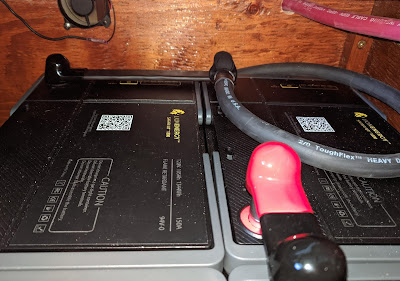
It was a good thing that Isaias was mostly a non-event, because I literally spent our entire time at the dock working on the battery system. And after testing most of the modes and functions, it seemed all was well, right up until we left the dock. I'm not sure whether it was unplugging shore power or starting the main engine that did it, but the new 300-amp circuit breaker tripped, fortunately before we cast off lines. I was able to just reset it and we carried on, but it left me scratching my head -- 300 amps is a lot of current for this system.
The reason for the trip soon became apparent when we did our first deep cycle of the batteries on our mooring ball back at the yacht club. This nominally 300a thermal breaker was tripping at just 90 amps of continuous current. After two consecutive trips during the charge process, I dialed the charge down to 70 amps or so. Knowing it was temporary, just until the AGMs are gone for good, and also redundant for the main Class-T fuse still in the ER, I had purchased an inexpensive off-brand breaker, and that proved to be a mistake.
 |
After getting the proper bolts I was able to boot the ground bus and clean it up. An exposed ground would have been fine; after all, the shunt is fully exposed. But this is cleaner and makes it consistent with the positive side.
|
With things working well enough, albeit with some work-arounds, we cast off our mooring in Portsmouth and headed north toward Portland, with an overnight stop at Wood Island. That's a relatively remote place, perfect for continued testing. It's great to once again have batteries that will carry us overnight and then some, without having to jump up first thing and start the generator, even before coffee.
Remaining issues.
Magnum got back to me, and the more permanent fix for the charger turns out to just be a new remote panel, a $210 item, which I immediately ordered to our next stop, Portland, on Amazon. They gave me a week-out delivery estimate, but there was really no other alternative. I also ordered a new circuit breaker, and the proper size M6 flange bolts, both of which were next-day items. And, of course, I started the return process for the crappy breaker that would only carry 90 amps.
I was able to hike up to the Amazon locker the day after we arrived in Portland, picking up my items and dropping off the return, and by mid-afternoon I had the new circuit breaker in, and the proper flange bolts installed. The new breaker, a 200-amp model that was of much beefier construction than the 300a item it replaced, had much larger 3/8 studs, vs. the 6mm ones on the cheap knock-off (and perhaps that should have been my first clue). That meant cutting off the 1/4" lugs and installing new 3/8" ones.
 |
The replacement breaker. This 200a model is beefier than the original 300a model, and had much larger 3/8" studs, compared to the 6mm (1/4") studs on the original item.
|
By some mysterious internal Amazon process, the delivery of the new inverter/charger remote got moved up from Friday to Monday, and so Tuesday morning I made another pilgrimage to the locker to pick it up. I had it installed in time to run a full charge cycle on the new settings, called "Constant Current to Constant Voltage" mode, and that's all working now, with the charge cycle starting right up once the genny is running.
The Link Pro battery monitor, however, is not coping well with these batteries. Its algorithms are really built around lead-acid chemistry, and there does not seem to be enough leeway in the settings to force it to do the right thing with lithium. I've finally got it dialed in to where the SOC% is close to correct most of the time, but the meter needs to be manually synchronized any time the batteries are fully charged, which, with these batteries, should only be at the dock or after several hours under way.
 |
| Post adapter. These should really be brass, not stainless, which conducts poorly. |
Speaking of under way, I've also had to adjust all the charge settings on our Balmar regulator for our main engine alternator. Those are mostly working correctly now, although I will need to install the alternator temperature sensor since the lithiums draw more current at low RPMs, where cooling is inadequate. I have the sensor available, having removed it from the batteries -- lithium batteries do not need, nor should they have, temperature compensation during charging.
Initial evaluation of Lion Safari batteries.
I had some trepidation ordering these after watching
this YouTube video from solar and lithium expert Will Prowse comparing their construction to the Battle Born product, and
this follow-on video tearing down the battery. Ultimately, though, these fit where the Battle Borns did not, and I am less concerned about environment and vibration in our saloon than many boaters would be in less controlled compartments. The lower price and excellent warranty also helped sway the decision.
That said, there have been a few issues to date:
- There is no date or version number on the user manual. I found multiple versions online, in addition to the printed version that arrived with each battery. Manuals should be dated so that users know they have the most up-to-date guidance on charge settings and other critical issues.
- The stainless steel post adapters are a design flaw. If post adapters are an integral part of the design, they should be nickel-plated brass.
- Wing bolts are not permitted or acceptable fasteners, and should be eliminated. Fasteners should ideally be hex-head, as this is most common for torque wrenches.
- No torque recommendation is provided for the fasteners.
- Charge setting recommendations are not clear and consistent, but ought to be. It's not even consistent throughout a single manual.
- The operating button and SOC display LEDs are in a direct line with the battery post, meaning they will be obscured by lateral bus bars.
- One battery arrived with its post adapters (which are shipped installed -- why?) dug into the packing foam, instead of positioned at the holes in the foam for this purpose.
- Answers from tech support were not confident or even correct. There was no acknowledgement or apology when confronted with the fact that they had provided incorrect dimensions, and no explanation for why the manual is inconsistent on settings.
- There is no SOC table nor any charge/discharge curves provided for these batteries. I had to extrapolate from data provided by other manufacturers or well-known parameters for LiFePO4 chemistry.
On top of the above, I can confirm the observations that Will made about the size of the terminals and quality of the casing. Not really a problem for us, but it gives me pause in recommending these batteries for most RV or marine installations.
 |
| The serial bus bars, atop the stainless post adapters, are the hottest things in the compartment. |
On the plus side, the built-in SOC meters are handy, I personally like button terminals for bus-bar applications, the cases are clean and functional, and, so far, performance is as advertised. Customer support, while not on top of their game technically, are at least very responsive.
I will be continuing to tweak charger, alternator, and monitor settings over the next few weeks as I build a charge/discharge profile from history. If all goes well, we will likely add two more batteries when they go on sale. The 210 aH will carry us for 12-14 hours under normal loads in temperate climates, and upping that by 50% will mean we will not have to run the generator at all when we travel every day, a feature we enjoyed with our AGM batteries when they were working properly.
Project Costs.
I bought manufacturer-direct using a discount code (and you can use my discount code, "6q" if you buy the same way, or use
this link). That brought the list price of $999 each down to $849 each, shipping included. The best price I could find from dealers was $899. Costco previously sold these for $699, but that deal is gone.
 |
| By contrast, the battery cases are much cooler. |
On top of the $3,400 for the batteries, I spent another $440 on parts, including cables, lugs, boots, bus bar, shrink tubing, bolts, a circuit breaker, and, of course, the new remote panel for the inverter. That does not count sweat equity or miscellaneous parts I already had lying around, such as the flushing fan. Call it $4k in round numbers.
If we actually get 3,500 cycles from these at 80% DoD each time, that would be 14,560 kWh stored/used over the course of their lifetime, for a cost per kWh of around 26.4 cents (yes, it really does cost twice as much as grid power just to store energy, and that's on top of whatever it cost to produce or buy to begin with). If we add two more batteries, that will decrease very slightly since I won't need more cables or another inverter remote.
 |
| New remote, showing the "Constant Voltage" mode charge for lithiums. Actual current into the batteries is shown on the SOC meter at left; the Magnum remote reads about 10% high, and some of the current is running DC loads. |
By comparison, our last set of AGM batteries cost $3,690 and delivered just 2,520 kWh, for a whopping $1.46 per kWh. The set before that probably delivered three times as much energy, although I failed to record it, for right around $3k, or about 40 cents a kWh. An optimistic view of the Lifeline ratings suggest they should have delivered at least twice what they did, but that's still expensive on a per-kWh basis.
Even if the lithiums do not deliver the warranted 3,500 cycles (and there is evidence they often deliver far more than that), our cost per kWh store should still go down. But beyond that, because the charge efficiency of these batteries is so much higher, with the charger running at full capacity from start to finish every time, our cost to produce that energy will also be lower. That cost, incidentally, is right around 80 cents per kWh at anchor. Solar power would be about a third of that and I really need to look into getting some panels.
 |
| Updated battery layout. I omitted the old batteries, still installed, but included their disconnect switch. The PowerMax charger shown is actually connected to the old bank for maintenance and will be moved as shown shortly. |
Appendix: Settings.
Some folks will inevitably ask, so here are the settings I am using right now for the three key devices. I expect to tweak at least some of these in the coming weeks, particularly the LinkPro meter:
Magnum MS4024 Inverter/Charger
Software version 5.5
ME-ARC remote, version 4.0
- LBCO 24.0 VDC
- VAC Dropout 80
- Battery Type CC/CV
- Max Charge Amps 120
- CV Charge Volts 28.2
- CV Charge Done Amps 30
- Max CC/CV Time 2.8 Hours
- Recharge Volts 26.0
- Max Charge Rate 100%
- Battery temperature sensor removed
Balmar MC-624 Regulator
Software version 3.0
- Basic Program P07 Halogen (my unit is too old to have an LFP program)
- Start Delay 45 Seconds
- Compensation Limit 29.2 volts
- Bulk Voltage 28.0
- Bulk Time (minimum) 12 minutes (the lowest that can be set)
- Absorption Voltage 27.8
- Absorption Time (minimum) 12 minutes
- Float Voltage 26.0
- Float Time (minimum) 12 minutes
- Battery temperature sensor removed
- Alternator temperature sensor installed
Xantrex LinkPro SOC meter
Firmware Version 1.06
- F1.0 Float (finishing) voltage 26.0
- F1.1 Charger ending current percent 2.5
- F1.2 Autosync Time 5 seconds
- F1.3 Discharge Floor 15%
- F2.0 Low SOC 15%
- F2.1 Low voltage 25.6
- F2.2 Low SOC clear 80%
- F2.3 Low battery alarm delay 10 seconds
- F5.0 Battery Amp-hours 210
- F5.4 Peukert Exponent 1
- F5.5 Self-discharge rate 0.2%
- F5.6 Charge Efficiency Factor 100%